Engineering, 14.06.2021 06:50 deena7
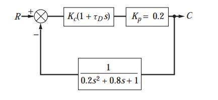
Plot the root locus diagram for the Plot the root locus diagram for the system shown in . We may consider this system to consist of a process having negligible lag; an underdamped, second-order measuring element; and a PD controller. This system may approximate the control of flow rate, in which case the block labeled K p would represent a valve having no dynamic lag. The feedback element would represent a flow measuring device, such as a mercury manometer placed across an orifice plate. Mercury manometers are known to have underdamped, second-order dynamics. Plot the diagram for t D 13 We may consider this system to consist of a process having negligible lag; an underdamped, second-order measuring element; and a PD controller. This system may approximate the control of flow rate, in which case the block labeled K p would represent a valve having no dynamic lag. The feedback element would represent a flow measuring device, such as a mercury manometer placed across an orifice plate. Mercury manometers are known to have underdamped, second-order dynamics. Plot the diagram for t D 13 .
Answers: 3


Another question on Engineering
Engineering, 04.07.2019 18:10
Items are similar to the free issue items, but their access is limited. (clo5) a)-bin stock items free issue b)-bin stock controlled issue c)-critical or insurance spares d)-rebuildable spares e)-consumables
Answers: 1
Engineering, 04.07.2019 18:20
The characteristic roots of a dynamic system are: 1.7920 1.8160 i, -1.7920 1.8160 i, -0.4160 what is the order of this system? what are the settling time and damping ratio of the system?
Answers: 3
Engineering, 04.07.2019 18:20
Asimple rankine cycle uses water as the working fluid. the water enters the turbine at 10 mpa and 480c while the condenser operates at 6 kpa. if the turbine has an isentropic efficiency of 80 percent while the pump has an isentropic efficiency of 70 percent determine the thermal efficiency
Answers: 1
Engineering, 04.07.2019 18:20
A2-m rigid tank initially contains saturated water vapor at 100 kpa. the tank is connected to a supply line through a valve. steam is flowing in the supply line at 600 kpa and 300 c. the valve is opened, and steam is allowed to enter the tank until the pressure in the tank reaches the line pressure, at which point the valve is closed. a thermometer placed in the tank indicates that the temperature at the final state is 200°c. determine (a) the mass of steam that has entered the tank (b) the amount of heat transfer.
Answers: 3
You know the right answer?
Plot the root locus diagram for the Plot the root locus diagram for the system shown in . We may con...
Questions


Social Studies, 24.11.2020 19:40

History, 24.11.2020 19:40
Mathematics, 24.11.2020 19:40
Social Studies, 24.11.2020 19:40
Mathematics, 24.11.2020 19:40

Computers and Technology, 24.11.2020 19:40


English, 24.11.2020 19:40
English, 24.11.2020 19:40