Engineering, 05.03.2020 16:46 TH3L0N3W0LF
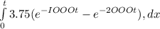
The voltage and current at the terminals of the circuit element in Fig. 1.5 are zero fort < 0. Fort 2 0 they areV =75 ~75e-1000t V, l = 50e -IOOOt mAa) Fund the maximum value of the power delivered to the circuit. b) Find the total energy delivered to the element.
Answers: 2


Another question on Engineering
Engineering, 03.07.2019 14:10
Explain the difference laminar and turbulent flow. explain it with the shear stress and the velocity profiles.
Answers: 1
Engineering, 04.07.2019 18:10
Apump is used to circulate hot water in a home heating system. water enters the well-insulated pump operating at steady state at a rate of 0.42 gal/min. the inlet pressure and temperature are 14.7 lbf/in.2, and 180°f, respectively; at the exit the pressure is 60 lbf/in.2 the pump requires 1/15 hp of power input. water can be modeled as an incompressible substance with constant density of 60.58 lb/ft3 and constant specific heat of 1 btu/lb or. neglecting kinetic and potential energy effects, determine the temperature change, in °r, as the water flows through the pump.
Answers: 1
Engineering, 04.07.2019 18:10
Fluids at rest possess no flow energy. a)- true b)- false
Answers: 3
Engineering, 04.07.2019 18:10
At 12 noon, the count in a bacteria culture was 400; at 4: 00 pm the count was 1200 let p(t) denote the bacteria cou population growth law. find: (a) an expression for the bacteria count at any time t (b) the bacteria count at 10 am. (c) the time required for the bacteria count to reach 1800.
Answers: 1
You know the right answer?
The voltage and current at the terminals of the circuit element in Fig. 1.5 are zero fort < 0. Fo...
Questions

Mathematics, 22.07.2019 04:30

Biology, 22.07.2019 04:30


Chemistry, 22.07.2019 04:30

Health, 22.07.2019 04:30

History, 22.07.2019 04:30
History, 22.07.2019 04:30
Mathematics, 22.07.2019 04:30

English, 22.07.2019 04:30

Mathematics, 22.07.2019 04:30

Mathematics, 22.07.2019 04:30